Building a Simple LED and Button Interface with Rust on ESP32
by Daniel Zelei
Sep 16
4 min read
1283 views
Previously, we set up a Rust development environment for the ESP32 microcontroller and successfully ran a "Hello World" program, culminating in flashing an LED. These exercises introduced the basics of embedded programming with Rust, highlighting how efficient and safe code can be written without the standard library. If you missed the previous section, you can read it here.
Now, we're going to make our project interactive by adding a button into the mix. By reading the button's input state, we'll control the LED—turning it on or off based on button presses. This tutorial will guide you through wiring the button, writing the Rust code to handle input, and integrating it all to create a responsive embedded system. Get ready to take your Rust and embedded systems skills to the next level!
Components needed
To set up this project, you will need the following components:
- ESP32 DEVKIT V1
- 5 mm LED
- 220 Ohm resistor
- Pushbutton
- 10k Ohm resistor
- Breadboard
- Jumper wires

Circuit Schematic
Before we dive into the code, here is the schematic for wiring the components:

It's straightforward to integrate the button and the LED into the ESP32. You only need the following code to make it work.
Code Implementation
#![no_std]
#![no_main]

use esp_backtrace as _;
use esp_hal::{
    gpio::{Input, Io, Level, Output, Pull},
    peripherals::Peripherals,
    prelude::*,
    system::SystemControl,
};

#[entry]
fn main() -> ! {
    let peripherals = Peripherals::take();
    let _system = SystemControl::new(peripherals.SYSTEM);

    let io = Io::new(peripherals.GPIO, peripherals.IO_MUX);
    let mut red_led = Output::new(io.pins.gpio5, Level::Low);
    let button = Input::new(io.pins.gpio4, Pull::Up);

    loop {
        if button.is_high() {
            red_led.set_high();
        } else {
            red_led.set_low();
        }
    }
}
Explanation of Pin Usage
In the schematic, we use GPIO4 and GPIO5 to connect the button and the LED, respectively. This is reflected in the code:
let button = Input::new(io.pins.gpio4, Pull::Up);
The button is connected to GPIO4, and it is configured as an input with a Pull-Up resistor. But why Pull-Up? A pull-up resistor ensures the button reads as "high" (logic level 1) when it is not pressed. When the button is pressed, the circuit connects to ground, pulling the signal low (logic level 0). This way, you can reliably detect button presses.
let mut red_led = Output::new(io.pins.gpio5, Level::Low);
The LED is configured as an output connected to GPIO5. We initialize its state as low, meaning the LED starts in an "off" state. But why low? This is because the LED is connected in such a way that setting the output pin to high will provide the voltage needed to turn it on, and low will turn it off. Starting in the "low" state ensures the LED is off at the beginning of the program.
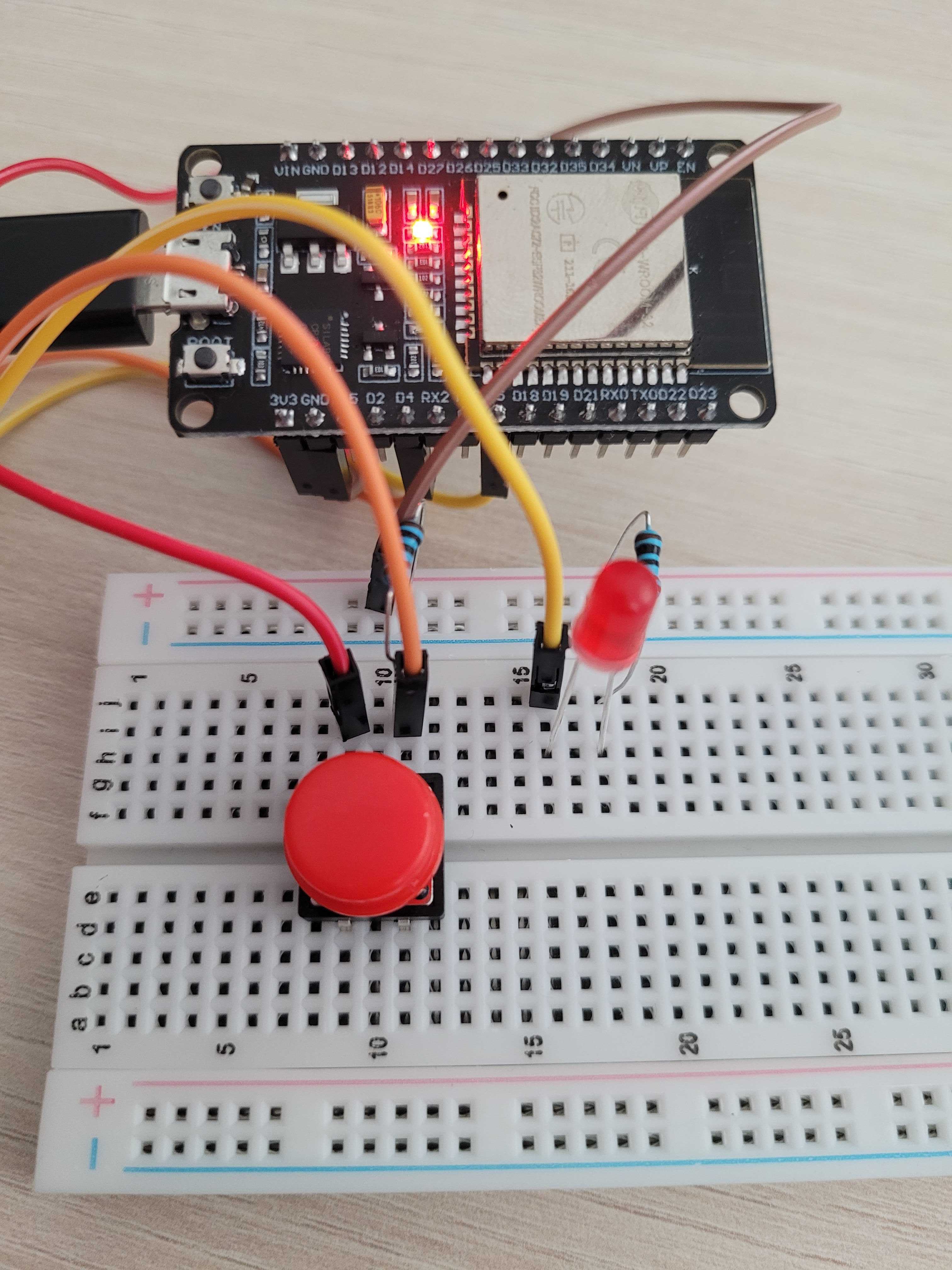
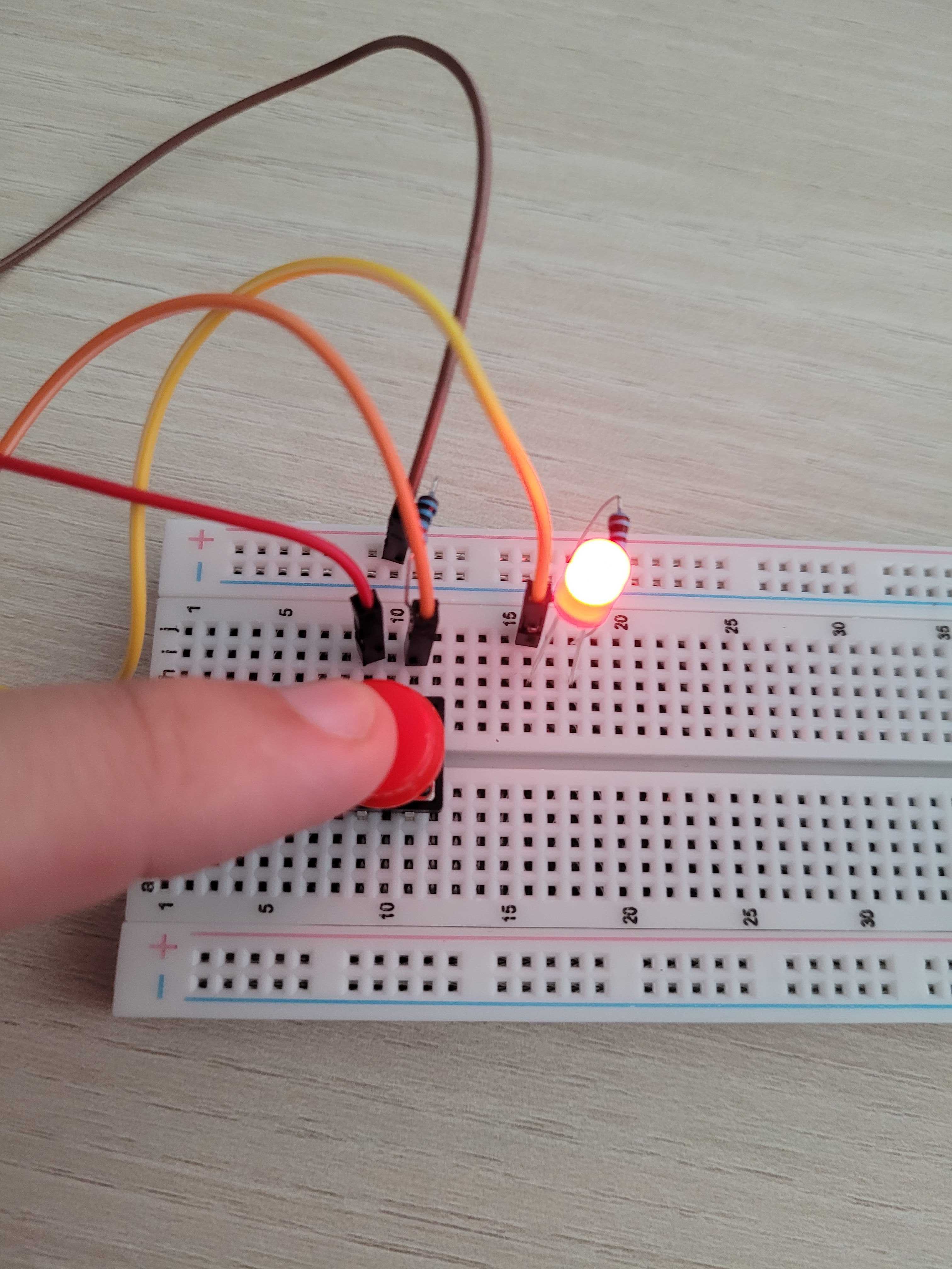
Visual Demonstration
Here are images showing how the project should look when completed:


Extending the Project: Adding a Second LED
You can see how easy it is to extend this project by adding a second LED. Let's modify the behavior:
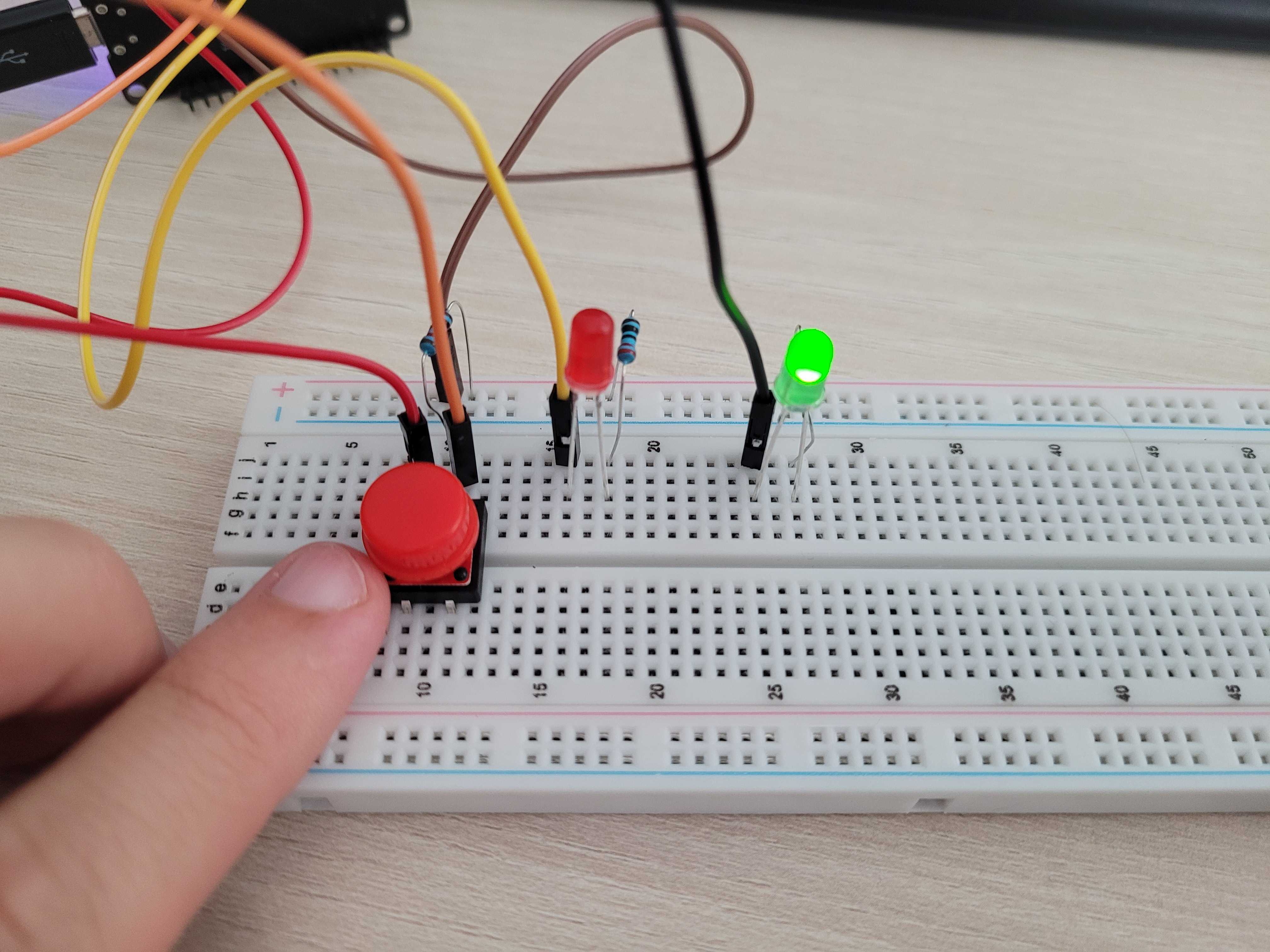
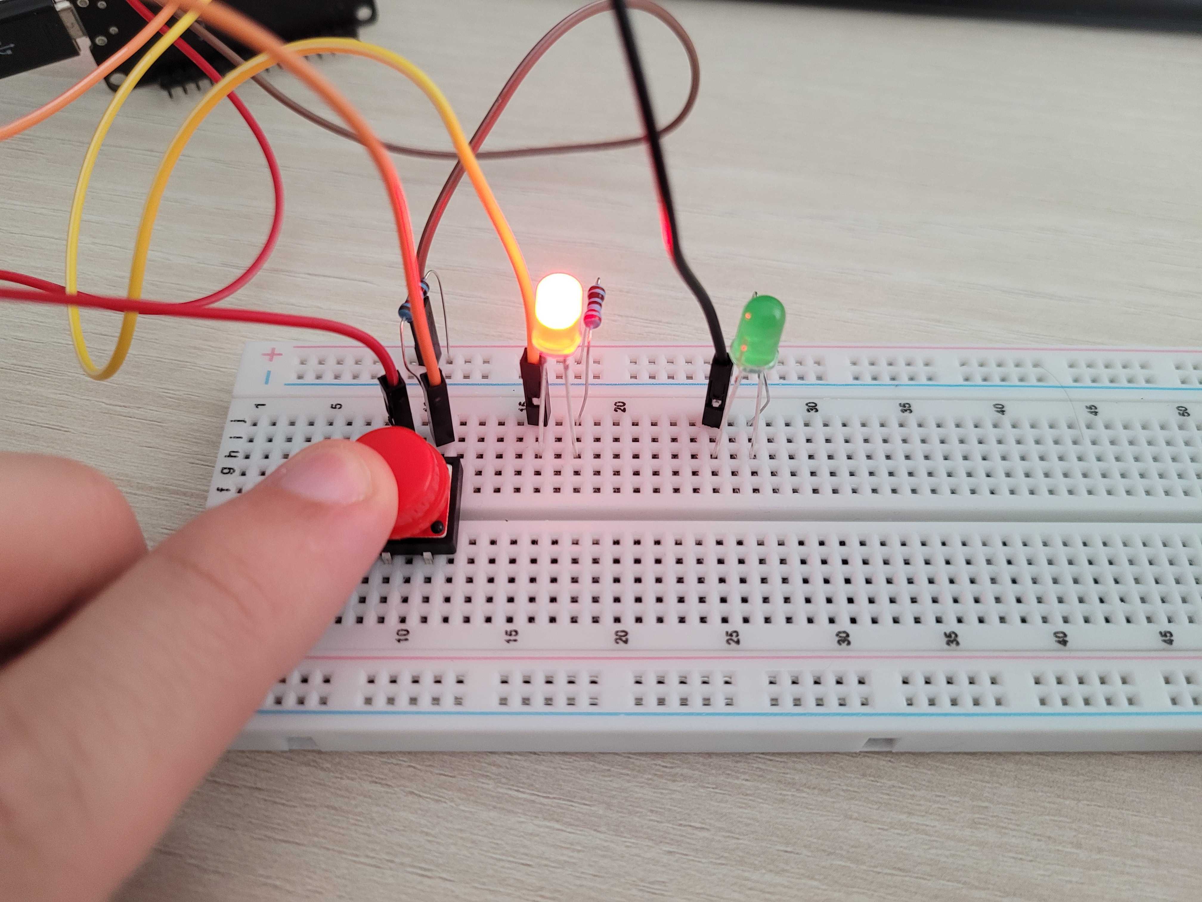
When the button is pressed, the red LED will light up (as it does now). When the button is not pressed, the green LED will be lit by default. In this case, I've connected the green LED to GPIO2. With this setup, pressing the button will turn on the red LED and turn off the green LED, while releasing the button will turn off the red LED and light up the green one.
Here’s the updated code:
#![no_std]
#![no_main]

use esp_backtrace as _;
use esp_hal::{
    gpio::{Input, Io, Level, Output, Pull},
    peripherals::Peripherals,
    prelude::*,
    system::SystemControl,
};

#[entry]
fn main() -> ! {
    let peripherals = Peripherals::take();
    let _system = SystemControl::new(peripherals.SYSTEM);

    let io = Io::new(peripherals.GPIO, peripherals.IO_MUX);
    let mut green_led = Output::new(io.pins.gpio2, Level::Low);
    let mut red_led = Output::new(io.pins.gpio5, Level::Low);
    let button = Input::new(io.pins.gpio4, Pull::Up);

    loop {
        if button.is_high() {
            red_led.set_high();
            green_led.set_low();
        } else {
            red_led.set_low();
            green_led.set_high();
        }
    }
}
How it Works
- GPIO2 is connected to the green LED, which is configured as an output.
- When the button is not pressed, the green LED is on by default (logic high).
- When the button is pressed, the green LED turns off, and the red LED turns on.
This simple extension demonstrates how you can control multiple LEDs with a single button, using Rust's no_std embedded environment.
Visual Demonstration
- Button Not Pressed (Green LED On):

- Button Pressed (Red LED On):

With just a few extra lines of code, you can expand this project to include additional components and behaviors. This flexibility is one of the advantages of using Rust in embedded systems.
Conclusion
In this post, we continued our exploration of embedded systems programming with Rust and the ESP32. Starting from the basics of controlling an LED with a button, we expanded the project to include a second LED, demonstrating how easily you can extend functionality by managing multiple hardware components.
We learned how to:
- Set up a button to control an LED.
- Understand the importance of input configuration with a pull-up resistor.
- Add a second LED and modify the code to control it based on the button's state.
This hands-on approach has shown how Rust’s no_std environment provides a safe, efficient, and flexible foundation for embedded systems development. Whether you are just getting started or looking to build more complex projects, working with Rust on microcontrollers like the ESP32 offers both performance and reliability.
Stay tuned for future posts where we'll dive deeper into more advanced topics, such as handling multiple inputs, controlling motors, or even connecting to Wi-Fi using the ESP32. Happy coding!